Filters
Why Is Filtering Important?
Filters can be found in almost any electronic device, and especially so in medical devices which handle lots of data and measurements. The primary goal of filtering in any system is to get rid of noise while preserving important data for use by physicians. This improves the signal to noise ratio (SNR) and makes signals more useful and easier to interpret for both people and other machines.
For example, filters are very useful in ECG readings. While the goal of an ECG is to detect electrical impulses from the heart rhymth, many other electrical signals can interfere such as muscle movements, including breathing, and even 60Hz AC currents nearby. Noisy signals are more difficult to understand and may even prove fatal if a physician cannot quickly and accurately diagnose a patient in events such as a heart attack.
What Are Filters And How Are They Applied?
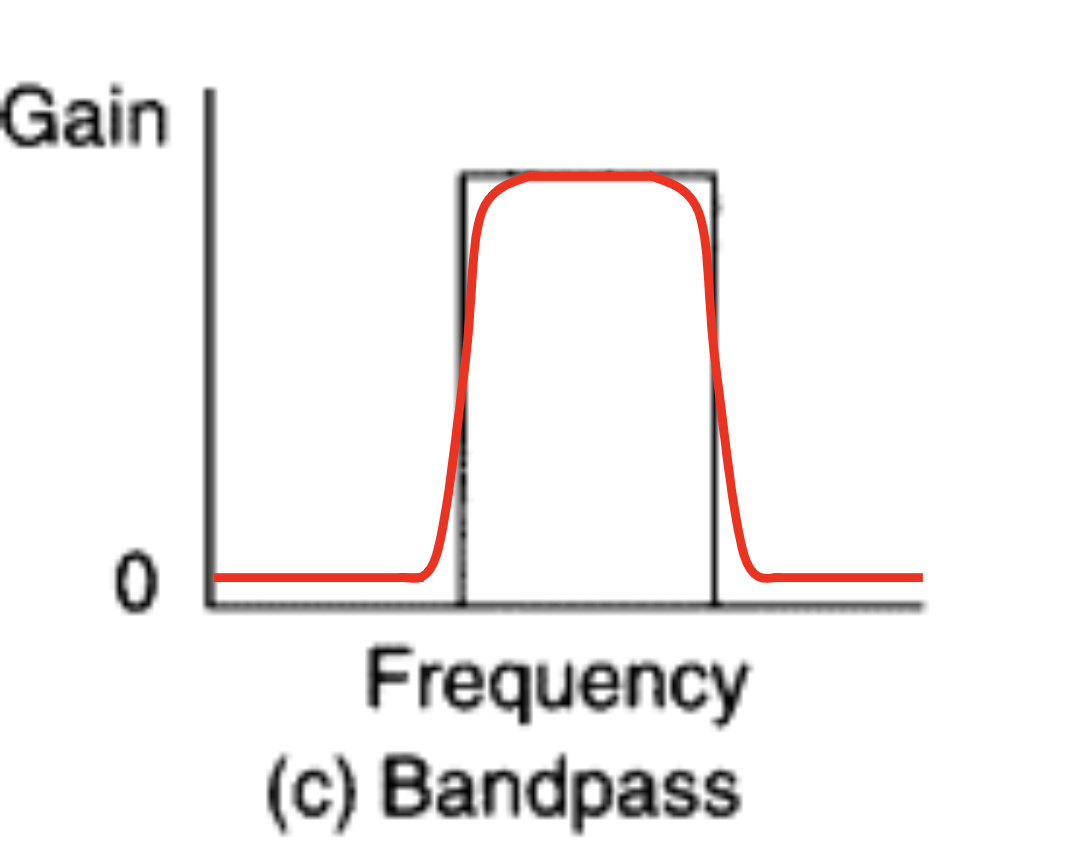
Filters are applied to frequency domain signals by attenuating (reducing amplitude of) sine waves within that range of frequencies. Different types of filters such as low pass, high pass, band pass, and band stop filters determine the range of frequencies which are attenuated.
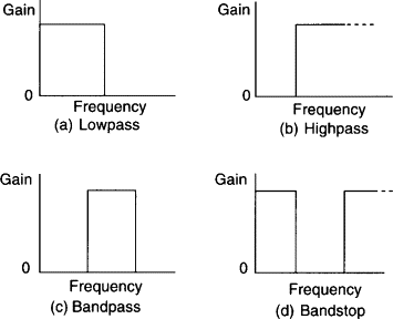
The example filters above are ideal filters, but because filters are made from combinations of physical electrical components, in reality, they do not have perfect attenuation at the cutoff frequency \( f_c \).
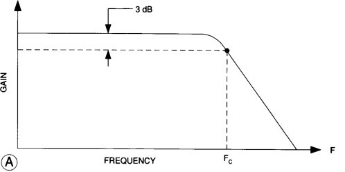
The ability for a filter begin acting within its cutoff frequency, or its quality, is measured by its Q factor. An example of a more realistic, imperfect filter is shown below.
The cutoff frequency of a filter is defined as the frequency at which the filter begins attenuating a signal at -3dB. Bandpass and bandstop filters have two cutoff frequencies, one high, and one low, which define the "band" within which the filter acts. The cutoff frequency for each filter can also be calculated using the values of the electrical components that make it up, the exact formulas are described below.
Gain and Decibels
How much the signal is attenuated is measured in voltage gain or decibel gain where voltage gain is a linear ratio of the amplitude of a signal before and after attenuation/amplification: \( \frac{V_{out}}{V_{in}} \) with a unit of V/V and decibels are: \( dB = 20log_{10}\left({\frac{V_{out}}{V_{in}}}\right) \) in relation to the gain with a unit of dB.
When a signal is amplified it has a voltage gain of greater than 1 and a positive decibel gain, and when it is attenuated it has a voltage gain between 0 and 1 and a negative decibel gain.
Filter Design
Below are diagrams of how different filters are constructed from different electrical components and shows how component values affect the behaviour of the filter.
| Filter Type | Circuit |
|---|---|
| Passive Lowpass |